What is a local thin area assessment?
A local thin area (LTA) assessment is an engineering check of whether pressure equipment with metal loss confined to one patch can stay in service, and for how long. It is part of fitness-for-service work, for which API 579-1/ASME FFS-1 is the joint API and ASME standard. It needs a thickness map of the patch, not single readings.
By Jun Zhong, Editor·Researched and drafted by Beacon's AI newsroom·Checked by Jun Zhong, Editor·Last checked ·Next review
Why does it matter?
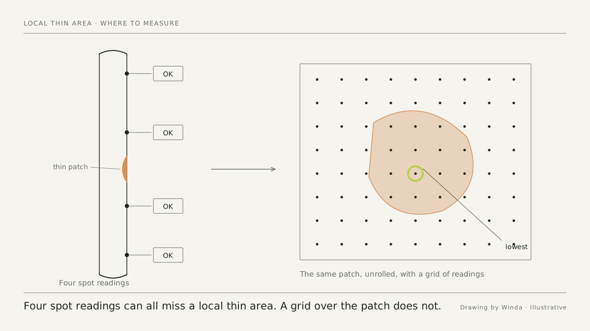
At a UK refinery, an 8-inch vertical relief line failed in normal operation and released about 75 tonnes of extremely flammable material 2. The UK Health and Safety Executive (HSE) found severe internal thinning very close to the break and roughly normal wall elsewhere along the line; thickness was tested regularly at four locations, none of them at the thinned area 2. A local thin area is easy to miss, so it is assessed as a patch with a shape and a position, not as one number.
What is a local thin area?
It is metal loss confined to one region of a vessel, pipe or exchanger, with sound wall around it, as opposed to thinning spread over the whole component. A 2025 assessment by a US Department of Energy laboratory treated the two separately, as general metal loss and local metal loss, on the same corroded heat exchanger 3.
Official cases show where local thinning develops and what drives it 2,3:
| Case | Where the thin area was | What drove it | How it came to light |
|---|---|---|---|
| UK refinery, reported 2019 2 | Part way along an uninsulated vertical relief line, a dead leg with little or no flow | HSE points to conditions found along dead legs, such as thermal gradients, deposits and liquid interfaces | The line ruptured; a neighboring relief line then showed similar hidden thinning |
| UK refinery, 2003 2 | Along a horizontal section of a relief line | A liquid interface in a partly filled line, and condensation near pipe supports | The line failed |
| US national laboratory, 2025 3 | Carbon steel end channels of water-cooled heat exchangers in service since the late 1990s | Untreated pond water, with no cathodic protection; deposits pointed to microbiologically influenced and galvanic corrosion | Inspection, after years with no documented inspection history |
Sources: HSE safety alert CEMHD2-2019 2; Fermilab slides, OSTI 2573808 3.
What data does an assessment need?
- A thickness map, not spot readings. In the 2025 case, wall readings were laid out on a two-dimensional grid and used to build a three-dimensional model of the corroded channel 3. HSE's alert says that for high-risk dead legs spot ultrasonic readings are not enough, and that a large share of the whole dead leg should be tested for remaining wall 2.
- Closer readings at the worst spot. The laboratory took extra measurements in a 4-inch square around the thinnest reading, because readings there varied by more than 10 percent 3.
- Design and operating data. The case lists the construction code, materials, pressures, temperatures, nominal wall and corrosion allowance 3.
- What else is nearby. The same exchangers had sharp grooves and weld metal loss at seam welds, assessed as a crack-like flaw, close to the tube sheet joint, which the engineers treated as a major structural discontinuity 3.
How is the assessment done?
API 579-1/ASME FFS-1, Fitness-For-Service, is the joint standard of the American Petroleum Institute (API) and the American Society of Mechanical Engineers (ASME); its 4th edition is dated December 2021 1. API describes fitness-for-service assessments as quantitative engineering evaluations of whether an in-service component with a flaw or damage can keep operating, and as support for run, repair or replace decisions 1.
The published 2025 case shows what such an assessment involves 3:
- Engineers mapped the wall thickness and modeled the real shape of the thinned channel. 3
- With no inspection history and a joint nearby, they used the most detailed form of assessment the standard offers. 3
- They ran an elastic-plastic stress analysis under the design-by-analysis rules of the ASME Boiler and Pressure Vessel Code, Section VIII, Division 2, and checked the wall against plastic collapse and against local failure. 3
- They assessed the weld flaw separately and added a leak-before-break analysis. 3
What can the outcome be?
- Fit for a stated period, with inspection. The 2025 exchangers were found fit for service at their original design conditions for 2.5 years, with an inspection at 1.25 years 3.
- Repair or replace. The same laboratory then planned to replace the corroded end channels and to fit sacrificial anodes 3.
- Run at lower pressure. US gas transmission rules allow corroded pipe to stay in service at an operating pressure reduced to match the strength of the remaining wall 5.
How are corroded pipelines handled?
US gas transmission rules take a related route. Pipe with corrosion that leaves less wall than its maximum allowable operating pressure needs must be replaced, repaired, or run at reduced pressure, with the strength of the remaining wall determined under 49 CFR 192.712 5. That section requires a suitable remaining strength calculation method, naming ASME/ANSI B31G and R-STRENG, or an alternative that is equally conservative; a method that could be less conservative needs advance notice to the Pipeline and Hazardous Materials Safety Administration (PHMSA), with comparisons and the burst tests used 4. See ASME B31G vs RSTRENG: how is corroded pipe assessed?.
Where integrity problems show up
| Decision | Data it depends on | What goes wrong without it | In the Library |
|---|---|---|---|
| Where to measure | A grid of readings over the suspect area | UK refinery: four regular thickness points lay either side of a very local thin area; the line ruptured and released about 75 tonnes 2 | What are condition monitoring locations (CMLs)? |
| How detailed the assessment must be | Inspection history, the spread of readings, welds and joints nearby | National laboratory, 2025: with no inspection history and a joint close by, the most detailed assessment was needed 3 | What is fitness-for-service (API 579-1/ASME FFS-1)? |
| How long the equipment can run | The assessment period and the inspection interval that goes with it | The 2025 result held for 2.5 years and required an inspection at 1.25 years 3 | Remaining life |
| Repair, lower pressure or keep running a pipeline | A remaining strength method, and the accuracy of the measurements fed into it | A 2003 riser study warned that limited measurement accuracy adds conservatism and can lead to replacing risers early, and that the methods need detail on spiral and circumferential defects 6 | ASME B31G vs RSTRENG: how is corroded pipe assessed? |
Sources: HSE safety alert CEMHD2-2019 2; Fermilab slides, OSTI 2573808 3; MMS TAP 433, 2003 6.
Common questions
- Does one low thickness reading mean the equipment must come out of service?
- Not by itself. In the 2025 case the thinnest reading was 0.097 inch on a channel with a nominal wall of 0.375 inch, and the exchanger was still found fit for 2.5 years, with conditions. The size and position of the thin area decide, and that takes an assessment.
- Is a local thin area assessment the same as ASME B31G?
- No. B31G and R-STRENG are remaining strength methods that US gas pipeline rules name for corrosion metal loss on pipelines. A local thin area assessment is the fitness-for-service check used for pressure equipment in plants.
Beacon explains these concepts in its own words for education. It does not reproduce or replace the standards cited, and Winda is not affiliated with or endorsed by the organizations that publish them. Engineering decisions need the current edition of the standard and a qualified engineer.
Sources
- 1.2025 Publications Catalog (entry for API 579-1/ASME FFS-1) (API 579-1/ASME FFS-1, 4th edition, December 2021) · American Petroleum Institute (API)
- 2.Catastrophic rupture of dead-leg pipe-work (Safety alert, Bulletin No. CEMHD2-2019) · UK Health and Safety Executive (HSE) ·
- 3.Fitness for Service Assessment of a Corroded Heat Exchanger (A. Humenik, E. Voirin), FERMILAB-SLIDES-25-0171-AD, OSTI 2573808 · Fermi National Accelerator Laboratory, US Department of Energy, via OSTI.gov ·
- 4.49 CFR 192.712, Analysis of predicted failure pressure and critical strain level · eCFR, US Office of the Federal Register
- 5.49 CFR 192.485, Remedial measures: Transmission lines · eCFR, US Office of the Federal Register
- 6.Evaluation of Methods for Detecting and Monitoring of Corrosion and Fatigue Damage in Risers, Final Report, TAP Project 433 · US Minerals Management Service, now Bureau of Safety and Environmental Enforcement (BSEE) ·