How are crack-like flaws assessed for fitness-for-service?
·Updated ·8 sources
A crack-like flaw is assessed by checking how close the cracked part is to fracture and to plastic collapse, usually on a failure assessment diagram. API 579-1/ASME FFS-1 and BS 7910 give such procedures. The inputs are the flaw's size and location, the stresses including weld residual stress, and the material's strength and toughness.
By Jun Zhong, Editor·Researched and drafted by Beacon's AI newsroom·Checked by Jun Zhong, Editor·Last checked ·Next review
Why does it matter?
On 25 July 2010 a 30-inch crude oil pipeline ruptured in a wetland in Marshall, Michigan, releasing an estimated 843,444 gallons of crude oil 1. The 51.6-inch crack-like feature that failed was one of six features an in-line inspection had found on that segment in 2005 1. The US National Transportation Safety Board (NTSB) found that the crack assessments took the tool's reported depths as exact, without its stated sizing tolerance, used a wall thickness 0.035 inch above nominal, which added about 14 percent to the pressure rating, and did not account for corrosion next to the cracks 1. Every one of those inputs is part of a crack-like flaw assessment.
What counts as a crack-like flaw?
API 579-1/ASME FFS-1 is the fitness-for-service (FFS) standard of the American Petroleum Institute (API) and the American Society of Mechanical Engineers (ASME); its 4th edition is dated December 2021 2. A 2025 assessment at a US national laboratory applied Part 9 of that standard, its part on crack-like flaws, to sharp grooves in weld metal 5. Flaws judged this way include cracks grown by stress corrosion, fatigue or corrosion fatigue 1,3. A 1990 review by the National Institute of Standards and Technology (NIST) found pressure vessel cracking concentrated at welds, especially welds never stress relieved, and in amine, wet hydrogen sulfide, ammonia, deaerator and pulp digester service 6.
How does a failure assessment diagram work?
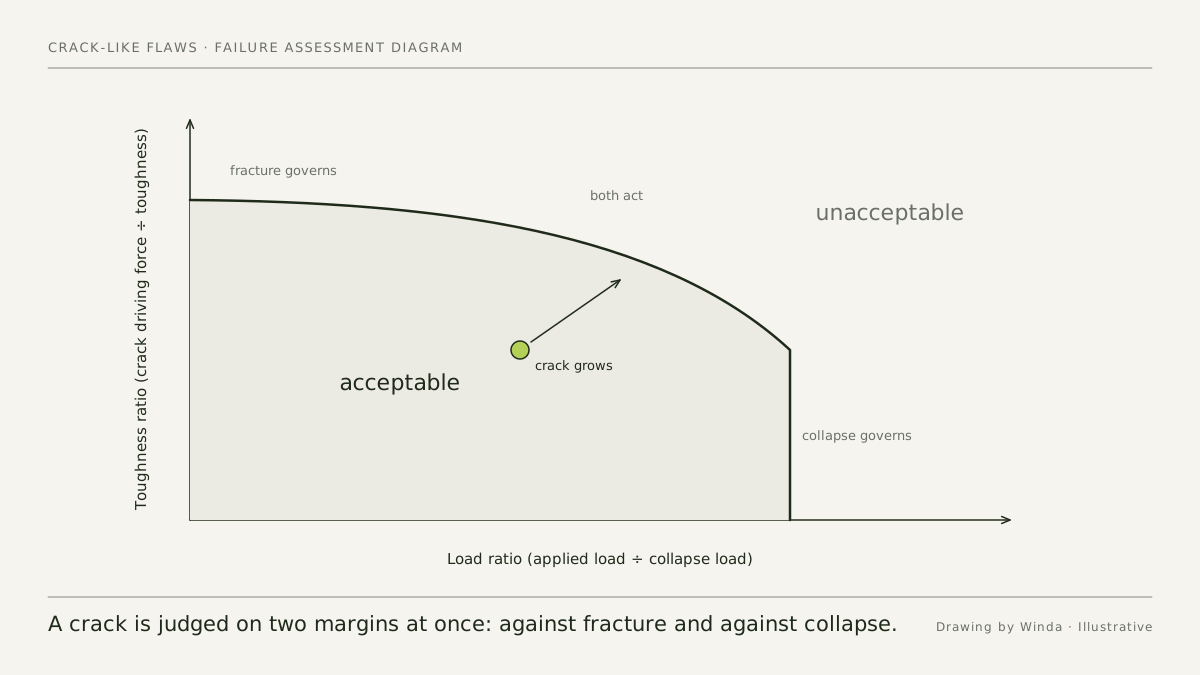
The usual tool is a failure assessment diagram (FAD). Two Savannah River National Laboratory (SRNL) reports describe it 3,4; the description below is in our own words and uses no figure from the standard. The diagram has two axes:
- Vertical: the toughness ratio. It compares the crack's driving force, expressed as a stress intensity, with the material's fracture toughness. A high value means fracture is close 3.
- Horizontal: the load ratio. It compares the applied load with the load at which the cracked section would yield right through. A high value means plastic collapse is close 3.
A curve runs across the diagram. The flaw's assessment point is acceptable inside the curve, critical on it and unacceptable outside it 3. Near the vertical axis fracture governs; far out along the horizontal axis collapse governs; in between, both act together 3.
What data does the assessment need?
- Flaw size, shape, orientation and location from nondestructive testing, with the sizing uncertainty. At Marshall the crack tool had a stated depth tolerance that the assessment left out, so some defects could appear smaller and stronger than they were 1.
- Wall thickness. A value above nominal raises the predicted failure pressure 1.
- Stresses, both primary, such as pressure and weight, and secondary, such as thermal stress and weld residual stress 3,4. A 2016 SRNL study found that adding weld residual stress, with elastic-plastic behavior through the FAD, gave much smaller critical crack sizes than a limit load method without residual stress 4.
- Material properties: yield and tensile strength, and fracture toughness. Where measured values are missing, specified minimum strengths and lower-bound toughness are used for a conservative answer 3. US gas transmission rules require conservative toughness values where toughness is not in traceable, verifiable and complete records (49 CFR 192.712(d)) 7.
- Corrosion beside the crack. At Marshall the crack tool measured depth from the corroded surface, so where corrosion overlapped a crack the true depth was greater than reported 1.
How do the three levels apply to cracks?
API 579-1/ASME FFS-1 offers three levels of assessment 8 (see What are the three levels of a fitness-for-service assessment?). Public documents show how the choice is made 3,4,5:
- In 2026, SRNL engineers followed the second level's FAD procedure for postulated surface flaws in spent fuel canisters 3.
- The 2016 SRNL study notes that the third level is the recommended choice when a crack can grow in service, and that one route at that level needs safety factors set by the user from a risk assessment; lacking those, the authors used the second level 4.
- In the 2025 national laboratory exchangers, the engineers' applicability check ruled out the first two levels because of the crack's length and its position at a tube sheet joint, so a third-level FAD assessment was used. A leak-before-break analysis followed: a crack assumed to run through the wall gave a rupture pressure far above anything the system could reach, while at normal operating pressure it would leak detectably 5.
- In July 2026 the US Pipeline and Hazardous Materials Safety Administration (PHMSA) proposed to name the second and third levels of API 579 among the technically accepted fracture mechanics methods for cracks in pipelines. It is a proposal, not yet a final rule 8.
How is remaining life estimated for a crack?
US gas transmission rules require operators, where fatigue or other loading can grow cracks, to use an applicable fatigue crack growth law, such as the Paris law, or another suitable method validated by a subject matter expert, and to define remaining life as the time until the crack reaches the size at which the pipe would burst at its maximum allowable operating pressure 7. After Marshall, the NTSB recommended a corrosion fatigue model for cracks in corroded areas when setting reinspection intervals 1. The 2025 exchangers were cleared for 2.5 years with inspection every 1.25 years 5.
Where integrity problems show up
| Decision | Data it depends on | What goes wrong without it | In the Library |
|---|---|---|---|
| Sizing the crack | Inspection sizes plus the tool's stated tolerance | Marshall, Michigan, 2010: depths used without the tolerance can make defects look smaller and their failure pressure higher than real 1 | Probability of detection (POD) |
| Wall and toughness inputs | Nominal wall and documented toughness | Marshall: a wall value above nominal added about 14 percent to the rating; US rules require conservative toughness where records fall short 1,7 | What is material traceability? |
| Stresses at welds | Weld type and heat treatment history | SRNL, 2016: weld residual stress greatly reduced the critical crack size in canister welds that were never stress relieved 4 | What is post-weld heat treatment (PWHT)? |
| Cracks inside corroded areas | Corrosion and crack inspection data overlaid | Marshall: no procedure accounted for wall loss beside cracks; the NTSB recommended including it 1 | What is corrosion fatigue? |
| Choosing the level | Whether, and by which mechanism, the crack can grow | SRNL, 2016: the third level where cracks can grow; NIST, 1990: cracking clusters in certain services and at welds without stress relief 4,6 | What is stress corrosion cracking (SCC)? |
Sources: NTSB/PAR-12/01, 2012 1; SRNL, OSTI 1254432, 2016 4; NIST SP 780, 1990 6; 49 CFR 192.712(d) 7.
Common questions
- Is BS 7910 the same as the API 579 crack procedure?
- No. They are separate documents from different bodies, though the NTSB described one pipeline operator's techniques as consistent with both BS 7910 and API 579-1/ASME FFS-1.
- Does finding a crack always mean a repair?
- No. NIST lists the options as running for a set interval, removing the damage without repair, or repairing it; cracks shallower than the corrosion allowance can be ground out and blended.
- What is the difference between a crack-like flaw and a local thin area?
- A local thin area is metal loss confined to one patch; a crack-like flaw is sharp and is judged by fracture mechanics. The 2025 national laboratory case had both on the same exchangers and assessed them separately. See [What is a local thin area assessment?](/library/local-thin-area/).
Beacon explains these concepts in its own words for education. It does not reproduce or replace the standards cited, and Winda is not affiliated with or endorsed by the organizations that publish them. Engineering decisions need the current edition of the standard and a qualified engineer.
Sources
- 1.Hazardous Liquid Pipeline Rupture and Release, Marshall, Michigan, July 25, 2010, Pipeline Accident Report NTSB/PAR-12/01 · US National Transportation Safety Board (NTSB)
- 2.2025 Publications Catalog (entry for API 579-1/ASME FFS-1) (API 579-1/ASME FFS-1, 4th edition, December 2021) · American Petroleum Institute (API)
- 3.Flaw Tolerance Assessment for DOE Standard SNF Dry Storage Canisters (X.-K. Zhu, R. Sindelar, B. Wiersma), WM2026 paper 26550, SRNL-STI-2026-00074, OSTI 3686268 · Savannah River National Laboratory, US Department of Energy, via OSTI.gov ·
- 4.Flaw Stability Considering Residual Stress for Aging Management of Spent Nuclear Fuel Multiple-Purpose Canisters (P.-S. Lam, R. L. Sindelar), Journal of Pressure Vessel Technology, SRNL-STI-2015-00680, OSTI 1254432 · Savannah River National Laboratory, US Department of Energy, via OSTI.gov ·
- 5.Fitness for Service Assessment of a Corroded Heat Exchanger (A. Humenik, E. Voirin), FERMILAB-SLIDES-25-0171-AD, OSTI 2573808 · Fermi National Accelerator Laboratory, US Department of Energy, via OSTI.gov
- 6.NIST Special Publication 780, Guidelines for Pressure Vessel Safety Assessment (S. Yukawa) · US National Institute of Standards and Technology (NIST)
- 7.49 CFR 192.712, Analysis of predicted failure pressure and critical strain level · eCFR, US Office of the Federal Register
- 8.Pipeline Safety: Repair Criteria for Hazardous Liquid and Gas Transmission Pipelines, proposed rule, 91 FR 42272, document 2026-13805 · US Pipeline and Hazardous Materials Safety Administration (PHMSA), Federal Register ·